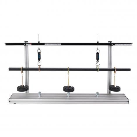
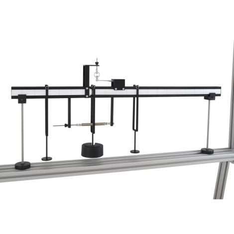
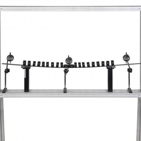
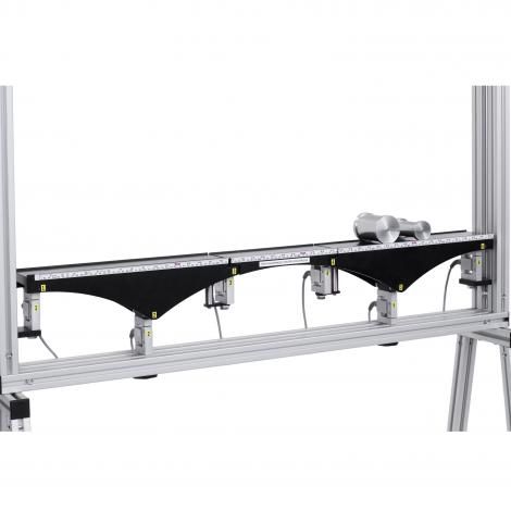
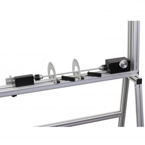
Reactions of Beams Apparatus
Experimental determination of the reaction forces in the supports of a simply supported beam under various loadings. Validation of the principal of equilibrium.

Triangle of Forces Apparatus
Allows for the study of three or more coplanar forces acting at a point, on a circular disc, or on a rectangular shape.

Polygon and Forces Apparatus
To resolve by experiment any suitable system of static coplanar forces which may or may not be concurrent.To verify graphically triangle of forces polygon of forces link polygon.
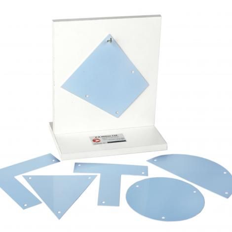
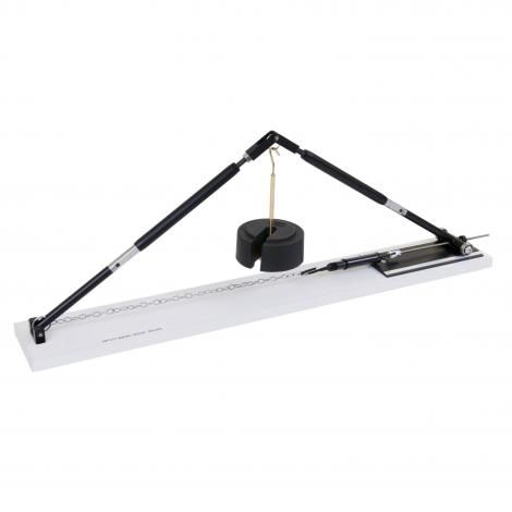
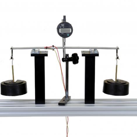
Centre of Gravity Apparatus
The centre of gravity of a shape of uniform thickness can easily be found by this apparatus. It provides a simple technique for complicated shapes, far quicker than using calculus for example.
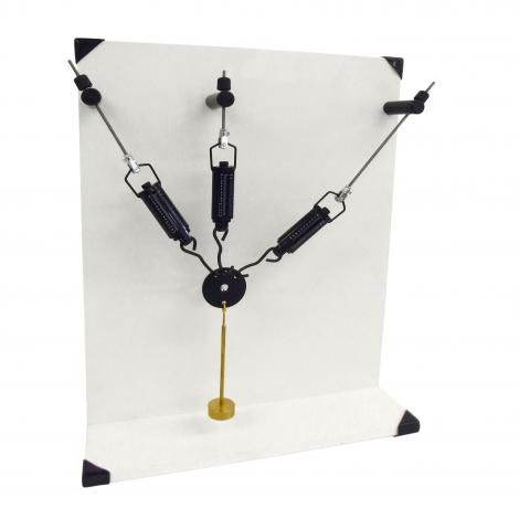
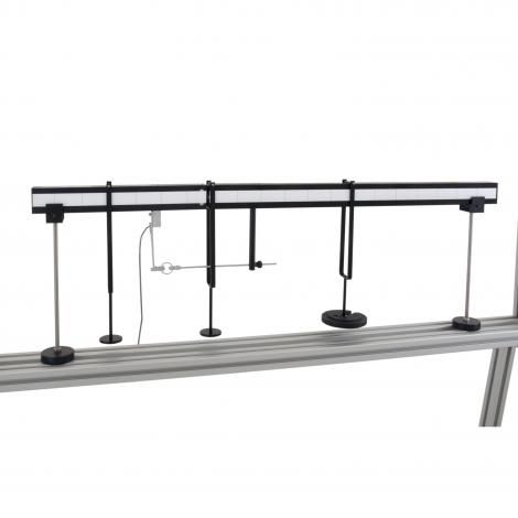
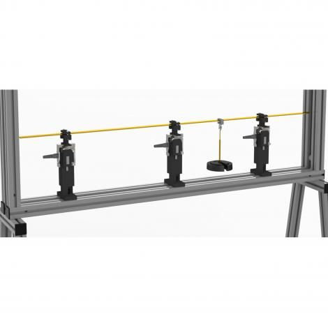
Three Wire Suspension Apparatus
To investigate the possibility of redundancy in the vertical tie. To compare the sum of the vertical components of the forces in the three wires with the vertical load they support.
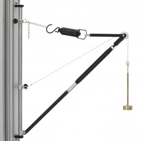
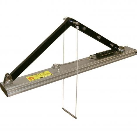
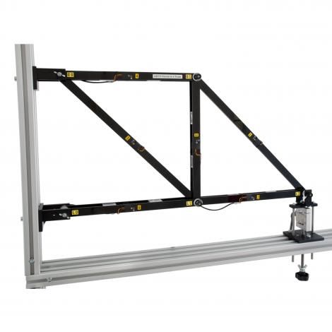
Wall Jib Crane
Determination of forces in crane members allows for the confirmation by theory and polygon of forces.
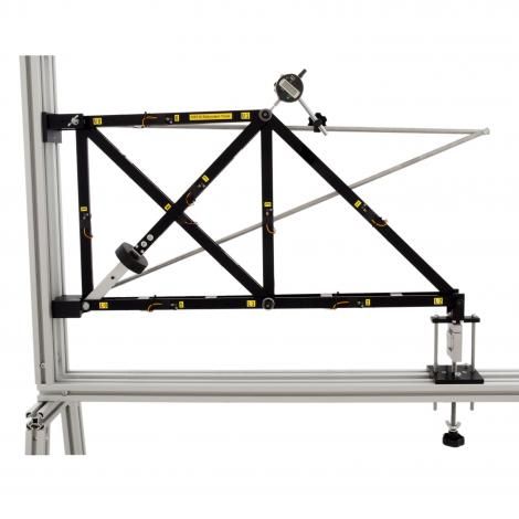
Derrick Crane
Determination of forces in the crane members; confirmation of theory, and polygon of forces.
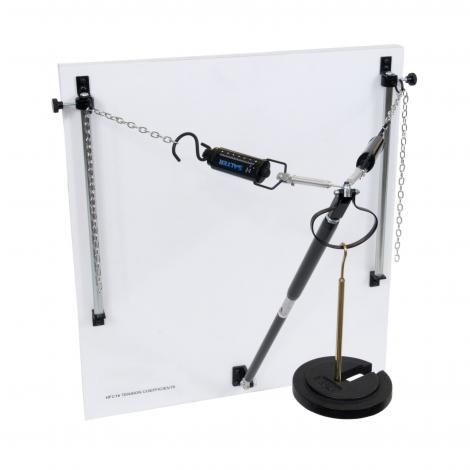
Tension Coefficients Apparatus
To determine experimentally forces induced in individual frame members.calculate the theoretical forces induced, using the method of tension coefficients.
Toggle Joint Apparatus
Determines the horizontal reaction due to loading a toggle joint mechanism; assesses the effect of the toggle angle.
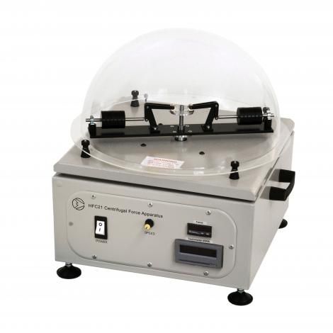
Centrifugal Force Apparatus
To verify that the centrifugal force on a rotating mass is proportional to the square of the speed, mass, radius of gyration.

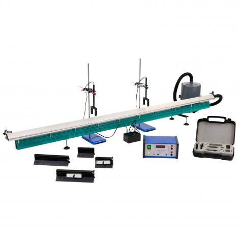
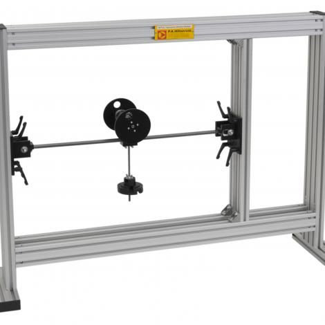
Coriolis Force Apparatus
To observe the Coriolis Force on a jet of water being rotated in a horizontal plane Effect of jet deflection as a function of boom rotational speed and the direction of boom rotation.
Combined Shear Force and Bending Moment Apparatus:
Allows for the study of both shear force and bending moment in a single compact unit. Shear Force and Bending Moment at a ‘cut’ section in a beam.
Conservation of Linear Momentum
Observe collisions between two trolleys, testing for the conservation of momentum Measure energy changes during different types of collisions.
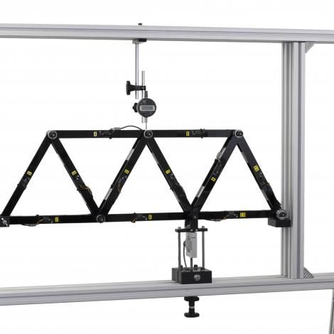
Basic Roof Truss
Experimental values of the forces in the struts and tie of a basic roof truss with theoretical predictions To observe the effect of changing the tie bar length.
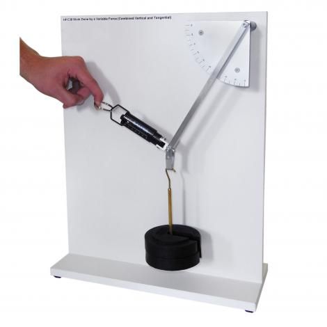
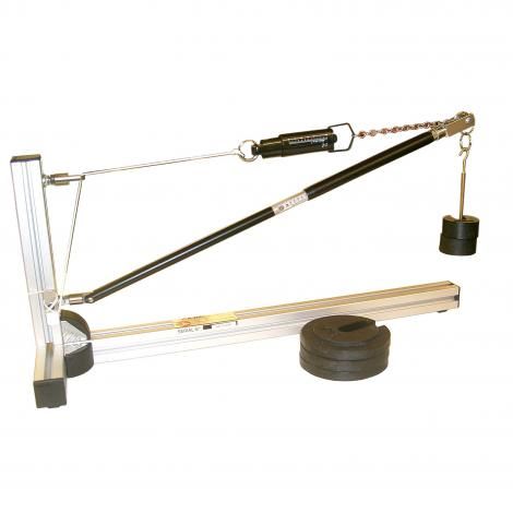
Work Done by a Variable Force (Combined Vertical and Tangential)
A single unit for experiments on mechanical work and potential energy. Lifting a weight using a lever and a dynamometer (spring balance) in both the vertical and tangential plane.
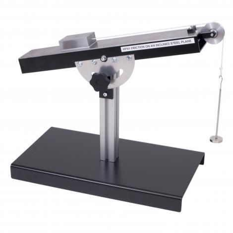
Friction on an Inclined Plane
A compact, bench mounted apparatus to measure the force required to move a body up an inclined plane and measure the friction coefficient for various materials in contact with that plane.
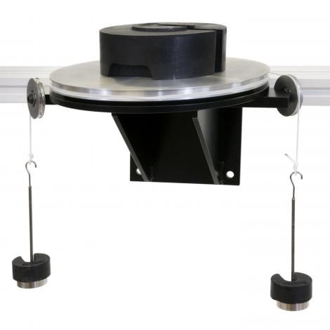
Clutch Plate Friction Apparatus
A self contained, wall mounted unit, to demonstrate and determine the coefficient of friction of brake lining material and minimum torque to maintain rotation.
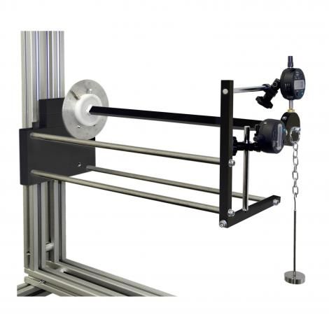
Pivot Friction Apparatus
A wall mounted apparatus that demonstrates the relationship between friction torque and axial thrust; determines the influence of bearing cone angle.
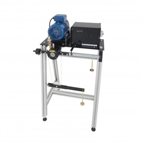
Journal Friction Apparatus:
Self-contained, free-standing, floor mounted unit driven by a speed controlled motor. Determines the friction torque under variable load , speed and lubrication.
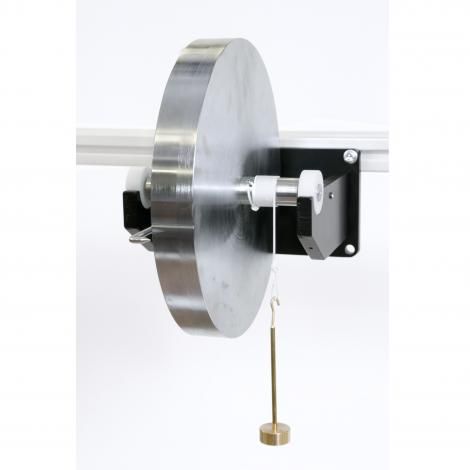
Bearing Friction Apparatus
Wall mounted unit to compare the frictional losses of bearings by measuring the coefficient of sliding friction between pairs of materials.
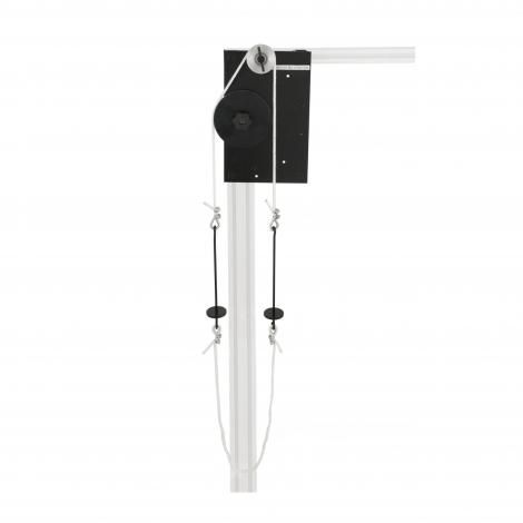
Rope Belt Friction Apparatus
A self contained, wall mounted unit for the effective determination of the coefficient of friction between a steel pulley and cotton rope. To also investigate belt tensions; evaluate effects of different `V` angles in a pulley, and of different lap angles.
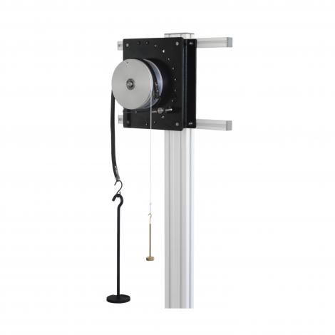
Friction of Belts Apparatus
A self-contained, wall mounted apparatus for determining relationship of friction in varying beltsdetermine the coefficient of friction between the pulley and belt for the belt sections Safety interlock to stop pulley rotating.
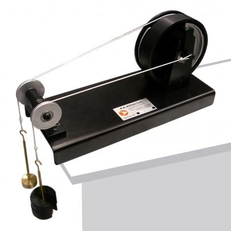
Brake Drum Friction Apparatus
A self contained, bench mounted apparatus, with a single leading and trailing shoe, for the study of coefficient of friction and determine experimentally the variation of tangential force with braking load.
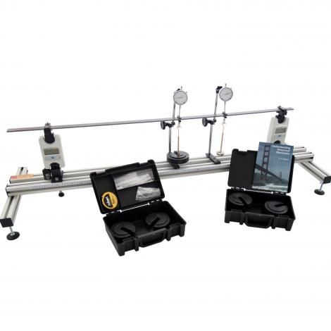
Deflection of Beams Apparatus:
Experiments to show, Deflection of a simply supported beam with varying span. Deflection for an offset load on a simply supported beam. Distributed Loads on a simply supported beam.
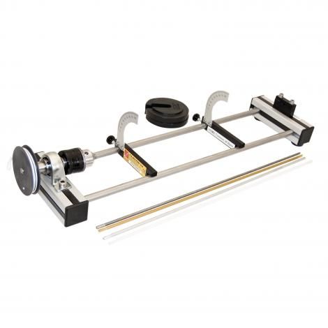
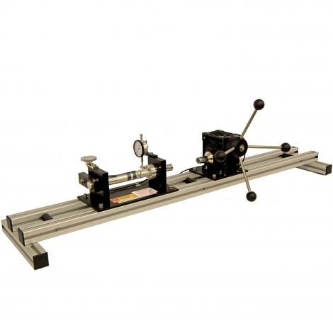
Torsion of Bars Apparatus
Apparatus to understand and investigate directly the relationship between the torsional load applied to a round bar and the angular twist produced and how this relationship varies with the beam material and it’s cross sectional polar moment of area.
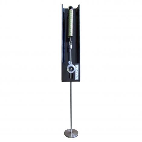
Extension of Springs Apparatus
To determine spring stiffness using measured spring data and load versus extension graphs. The dependence of spring stiffness on the wire diameter, spring diameter, length, number of turns and material can be calculated.
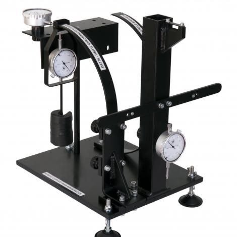
Curved Bar Apparatus
To experimentally determine the vertical and horizontal deflections of various curved bars whose cross sectional dimensions are small compared with the bar radius
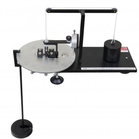
Combined Bending and Torsion Apparatus
A self contained, bench mounted apparatus to determine elastic failure of a specimen subjected to several ratios of simultaneous bending and torsion : allowing comparison of results with the established theories of failure.
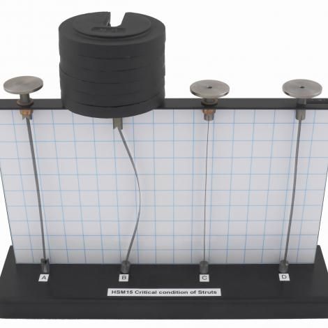
Critical condition of Struts
To observe the behaviour of four struts of the same length, but with different end constraints, when subjected to buckling loads. Compare the results with theoretical predictions, such as Euler’s formula.
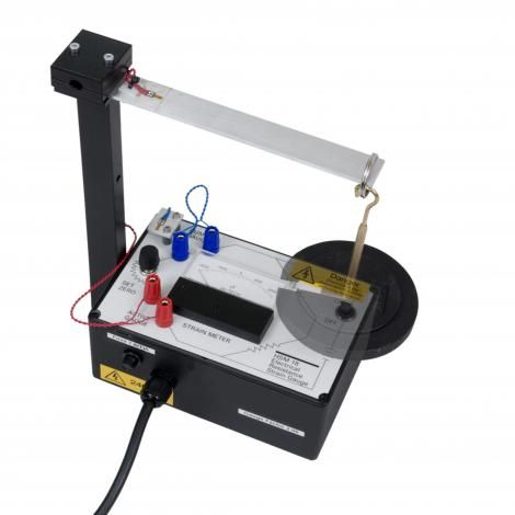
Electrical Resistance Strain Gauge
The apparatus has been designed to illustrate the basic features of electrical resistance strain gauges and their application in measuring bending and torsion.
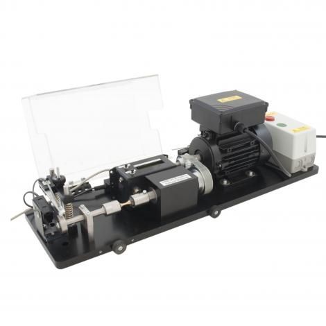
Rotating Fatigue Machine
This unit has been designed to introduce students to the effects of material fatigue using a sinusoidal variation of bending stress. Comes complete with data logging functionality.
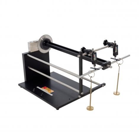
Unsymmetrical Cantilever Apparatus
This apparatus allows the vertical and horizontal deflections of the free end of a test specimen to be measured when loading occurs along a principle axis or at a known angle.
Torsion Testing Machine
Torsion testing machine for destructional testing of steel, brass and aluminium samples. Strain gauge technology is used within the torsion head and the output from these strain gauges.

Pendulum Impact Tester
A study bench top mounted unit for the study of notched bar (Charpy) impact strength tests. A heavy base plate with protective guard surrounds all the components Lockable door and brake mechanism.
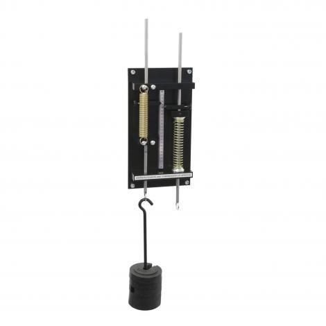
Extension and Compression of Springs
Wall mounted apparatus to demonstrate Hooke’s law and the relationship between deflection and load for tension and compression springs.
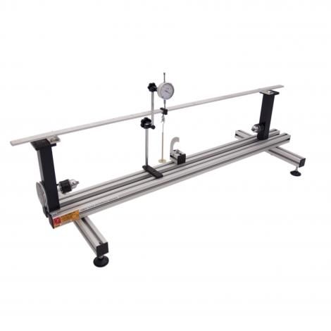
Torsion and Deflection Testing Apparatus
This bench top unit allows a variety of experiments to be undertaken to investigate test specimens under torsional loading and bending loading within their elastic limits.
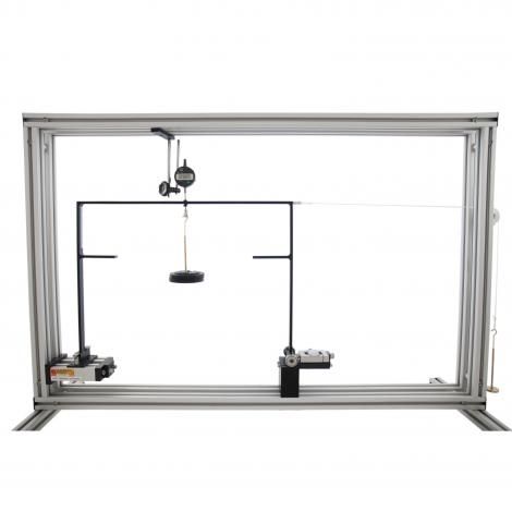
Three Hinged Arch
To study the Relationship between horizontal thrust at arch springing for varying applied load Understand characteristics of symmetrical &unsymmetrical three pinned arch.
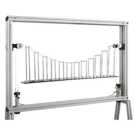
Simple Suspension Bridge
Comparison of theory with actual results for a uniformly distributed load and point load and rolling load .Cable tension obtained for loads at varying positions and magnitude along the bridge deck.
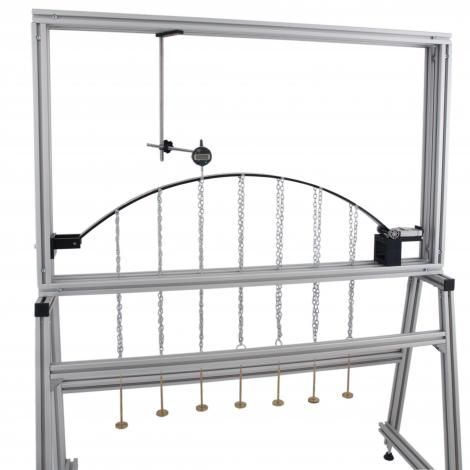
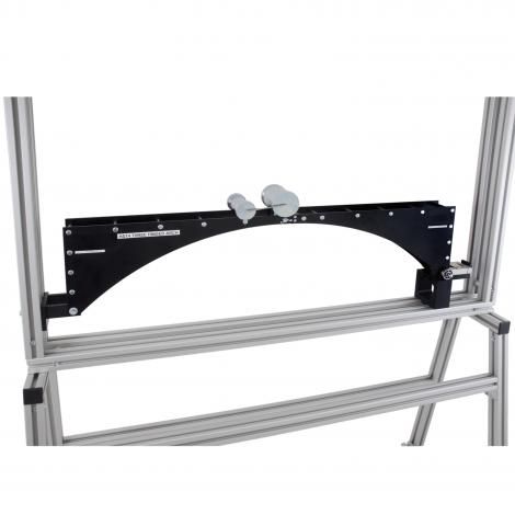
Two Hinged Parabolic Arch
To study relationship between applied loads and horizontal thrust ,Comparison of horizontal thrust at springing with simplified theory Verifies model analysis theory.
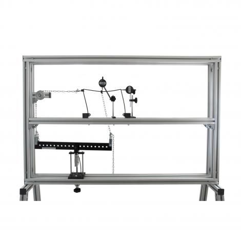
Deflection of Frames
Study the load, horizontal thrust, deflections, sway in portal frames .Comparison of experimental results with theoretical values derived using Castigliano’s theorem and numerical analysis by Simpson’s rule.
Plastic Bending of Portals
Studies the change in the collapse mechanism as the ratio of horizontal to vertical load is varied Verifies that hinges occur at positions of greatest bending moment.
Shear Force in a Beam
Shear force variation with varying point loads, load positions and load arrangements. Visual demonstration of shear force at a ‘cut’ in a beam.
Bending Moment in a Beam:
Shear force variation with differing load points, positions and arrangements Visual demonstration of shear force at a ‘cut’ in a beam .Law Bending Moment Diagrams Young’s’ Modulus Verification of Equilibrium of Vertical Forces and Moments.
Continuous and Indeterminate Beams:
Study of the general formula for beam deflections in bending in the form y= c Verification of the effect of changing the length of the beams The principle of superposition Indeminate Beams Cantilevers and Propped Cantilever.
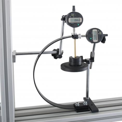
Deflection of Curved Bars
Comparison of experimental results with those derived by exact and approximate methods of analysis Use Castigliano’s rule and Simpsons rule Deflection of free end analysed using twin displacement gauges.
Deflection of Beams and Cantilevers
Measure beam deflections for point and uniformly distributed loads. Verify differential equation for beam bending. Measure and calculate slope and end rotations.
Redundant Truss
Study of deflection of a truss with and without redundancy Study of strains, forces and deflections in a determinate and indeterminate framework.
Forces in a Truss (Resolution)
Measure strains exerted on each truss member Calculate member forces by resolution of joints To view compressive and tensile forces/strains.
Suspended Centre Span Bridge
The model three span bridge has a flat deck and solid spandrels to the three spans. Use of the influence lines for a tandem rolling load Production of influence lines for all six reactions.
Pin Jointed Frameworks
To study of strains and Stresses within various true pin jointed frameworks Comparison of actual and theoretical results.Using Law Castiglianos’ Theorem Modulus of Elasticity. Reactions. Bow’s notation.
Unsymmetrical Bending & Shear Center
Study of the horizontal and vertical deflection of asymmetrical cantilevers when the plane of loading does not coincide with a principle axis of the section, neutral axis in an angle section & Shear Centre in U channel section.
Torsion of Rods and Tubes
Theory of torsion in circular section rods and tubes Comparison of the extended theory of torsion for a hollow square section member using Law Modulus of Rigidity Polar moment of inertia.
Strain Measurement for Structures
Determination of the gauge factor materials with strain / stress conversion using Young’s Modulus. Different Clamp Arrangements.
Equilibrium of Forces
Equilibrium of a set of forces acting in a vertical plane Equilibrium of up to six concurrent and non-concurrent forces Graphical solution of a triangle of forces.
Buckling of Struts
Varying end conditions and strut length against Euler’s buckling load Off-centre Strut loading.

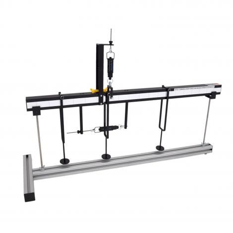
Combined Shear Force & Bending Moment
Visual demonstration of the Shear Force and Bending Moment at a ‘cut’ section in a beam .Variation in bending moment for variations in load, load position and load arrangement.

DIGITAL INTERFACE HDA200
The HDA200 Interface is supplied in a corrosion resistant metal enclosure, with rubber feet for bench top mounting. A frame mounting bracket is also supplied for mounting onto the HST1. The LCD has an excellent viewing angle.
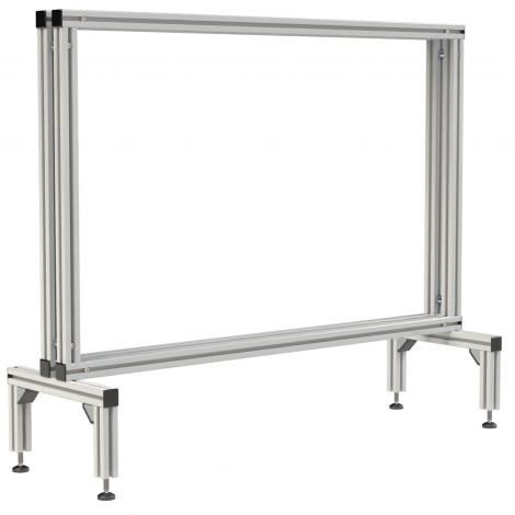
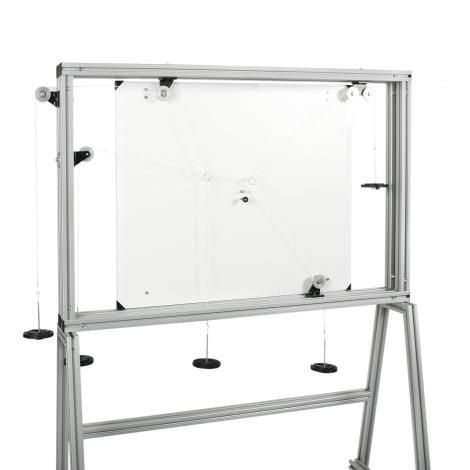
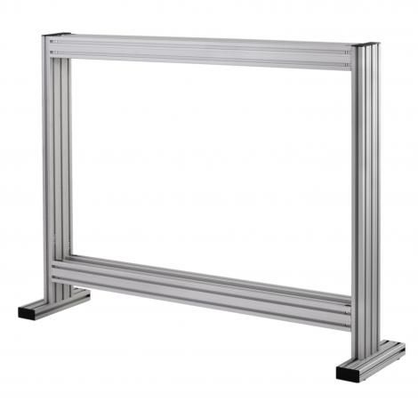
BENCH MOUNTED FRAME
Bench mounted frame offers the ideal working area for assembling and operating a large majority of the Structures range of experiments. Manufactured from high quality, aluminium profile, it comprises a dual frame, which creates a continuous mounting slot around all four sides of the frame.
Compound Pendulum
A wall mounted apparatus to determine the radius of gyration and centre of gravity of a compound pendulum. Investigations also include the effect of fulcrum position, finding gravitational acceleration ‘g’, and comparison with a simple pendulum.
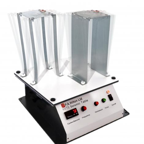
Seismic Table
A bench mounted uniaxial motion simulator allowing some of the fundamental concepts of structure design and designing principles to be investigated. Topics as resonance, dampening, torsion, material properties and end condition fixings.
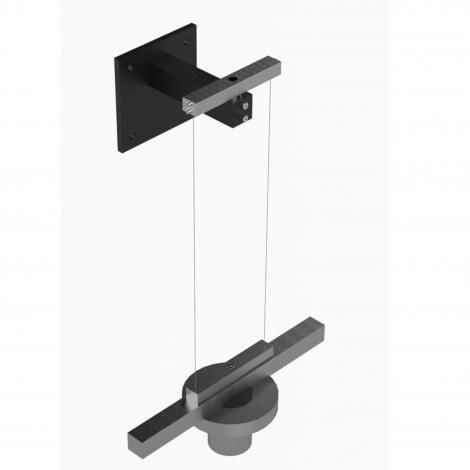
Bifilar / Trifilar Suspension
Both Bifilar and Trifilar setup apparatus to determine experimentally the moment of inertia and radius of gyration of a rectangular bar, ring and cylinder.
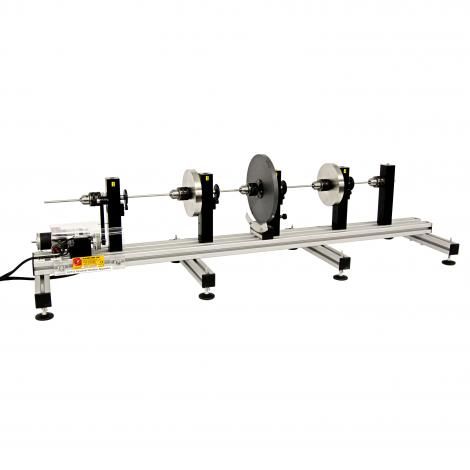
Torsional Vibration Apparatus
A bench top unit for investigating torsional vibration and stiffness and demonstration of the effect of frictional damping.
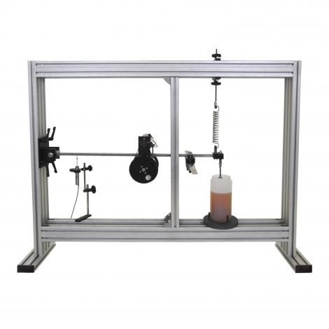
Universal Vibration System
To allow the study of free and forced vibration, resonance and damping Kit ,Natural Frequency A damping absorber is also supplied that attaches to the beam, and can be adjusted.
Beam Bending
A flexible beam supported between two end brackets which create simply supported end conditions. Allowing the study of free and forced vibrations, resonance, amplitude and phase lag.
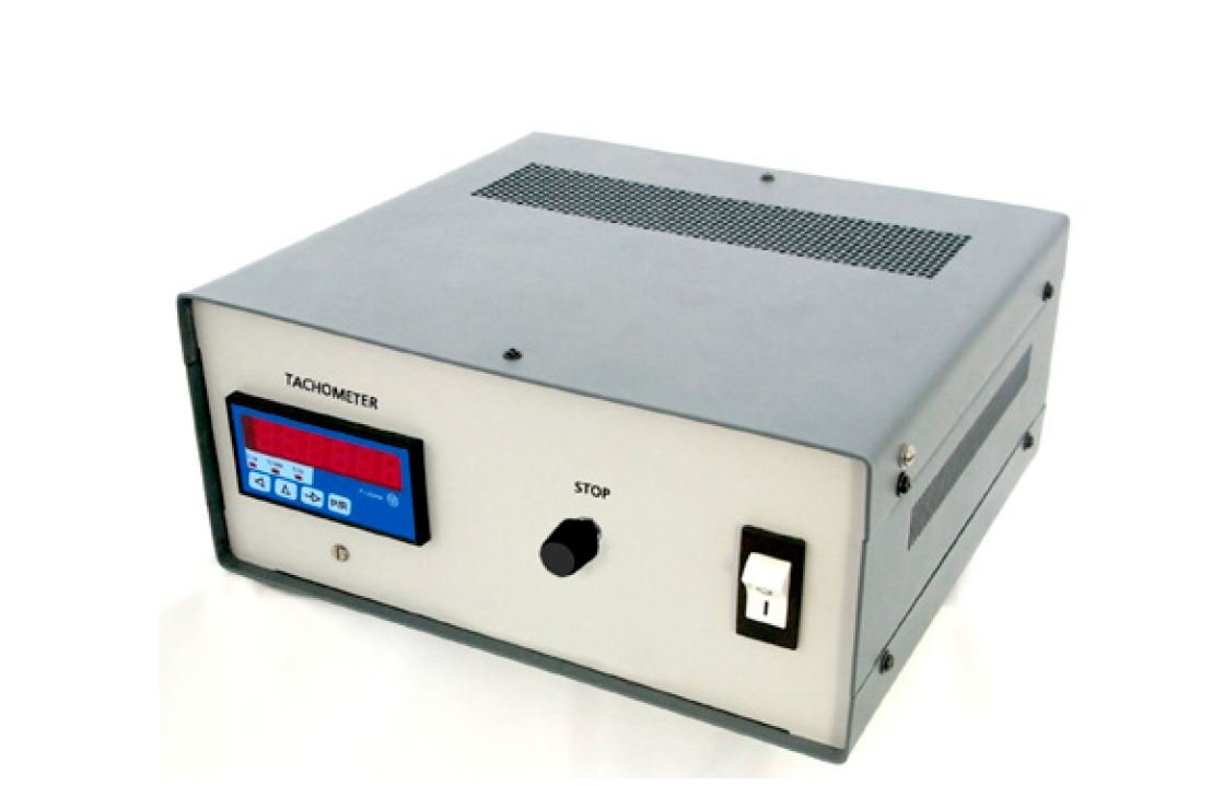
Tachometer
Displays the excitation force frequency as part of the HVT12G free and forced vibrations experiment. Unit to control the rotational speed of the motor exciters used on the HVT12C and HVT12G.The unit connects directly to the HAC90 tachometer.
Torsional Oscillation Module
Accessory to verify the dependence of the periodic time of oscillation of a “shaft” mounted flywheel on the moment of inertia, length of shaft, and shaft diameter . Allows the study of the modulus of rigidity and effect of damping.
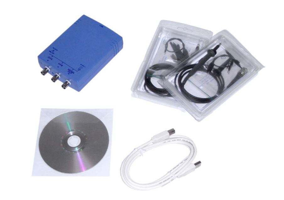
Data Acquisition System
Two channel digital oscilloscope and software allows the capture, display, storage and retrieval of the excitation frequency and beam response from the HVT12 apparatus.
Vibration Frame
HVT12 Universal Vibrations Apparatus Modules are all mounted within the HVT12f Vibration frame